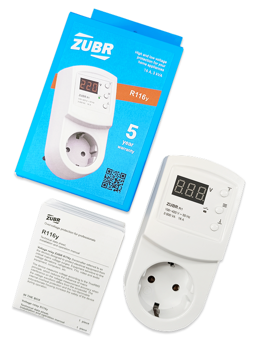
Welcome to installation and operation web manual for ZUBR R1

Voltage monitoring relay

— Protect electrical equipment from critical mains voltage surges. Equipment sensitive to line voltage deviations: refrigerators, TVs, video and audio equipment, computers, etc.

Content

Content

Purpose

Purpose

Why do professionals choose ZUBR? ‍The device measures voltage with high accuracy using the TrueRMS algorithm, which significantly improves the accuracy of voltage measurement in the event of interference in the network in cases where the voltage waveform differs from the sine wave.

The body of the device is made of non-combustible polycarbonate, which is the best type of plastic for fire protection requirements. For additional protection against overheating in case of poor contact between the relay and the connected device, there is a temperature sensor inside.
read more
All settings are securely stored in non-volatile memory in the event of a power outage.

‍The durability and reliability of the power relay contacts is ensured by switching on the load as close as possible to the moment when the voltage sine wave passes through zero. Small deviations from the zero crossing are possible due to the different tripping times of different device samples.

‍Please read this document in its entirety before installing and using the device. This will help to avoid possible hazards, errors, and misunderstandings.

Do not use the device ‍to protect equipment powered by modified sine wave sources or uninterruptible power supplies whose output voltage is not sinusoidal. Prolonged operation (more than 5 min) from such voltage sources may damage the device and lead to non-warranty repairs.

close

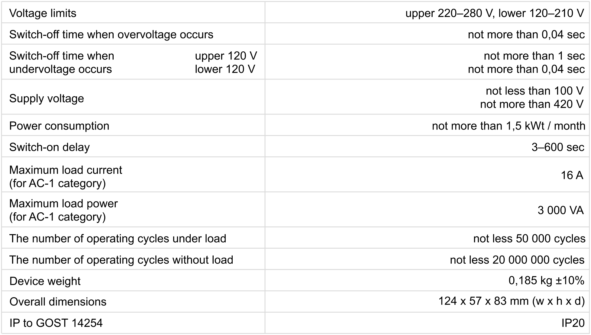
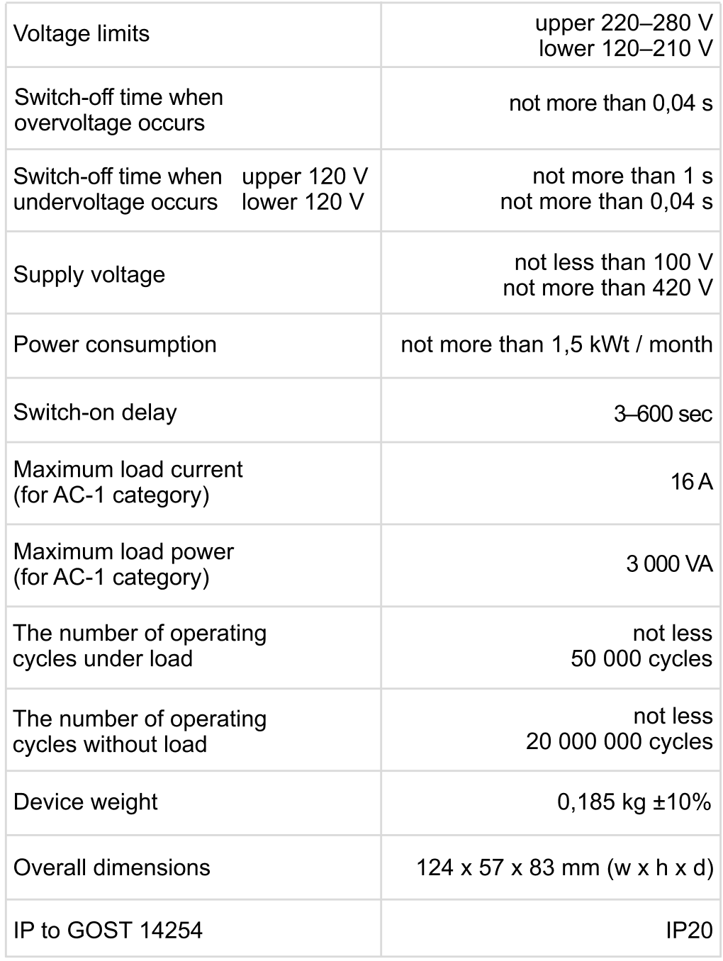
Technical data

Technical data

read more
The number of operating 
cycles under load
100 000 cycles
not less 10 000 cycles
The number of operating 
cycles without load
1 000 000 cycles
not less 500 000 cycles
Relay type
electro-
magnetic
polarized
Current measurement 
accuracy
0,5–63  А ±0,1–0,3 А
Voltage limits
upper 230–280 V,
lower 100–210 V
Switch-off time when
overvoltage occurs
not more than 0,03 sec
Switch-off time when
undervoltage occurs
0,1–10 c  | ≥ 100 V |
not more than 0,03 с  | < 100 V |
Supply voltage
100–420 V
Power consumption
not more than 0,35 kWt / month
Connection
wire cross section not more than 16 mm2
Device weight
0,19 kg ±10%
Overall dimensions
36 х 85 х 66 mm  (w х h х d)
IP to GOST 14254
IP20
close

Installation

Installation

The device is intended for indoor installation. Minimize the risk of moisture and liquid ingress at the installation site. The ambient temperature during operation and installation should be between –5...+45 °С.
The device is installed in a socket, which must be protected against short circuit and overcurrent by a circuit breaker (CB) with a rating of no more than 16 A.

‍The circuit breaker is located in the switchboard and mounted in the phase wire break.

‍To protect against overvoltage caused by lightning discharges, it is necessary to use arresters together with the device. They are installed at the entrance to the building in accordance with their instructions.

‍To protect a person from electric shock in the event of a leakage, an RCD (residual current device) is installed in the electrical distribution panel.

‍The wiring to which the device is connected must correspond to the power consumed by the load.

Exploitation

Exploitation

‍When connected and during operation, the thermostat displays the current temperature of the remote sensor. If it is lower than the set temperature, the load is energized. In this case, the indicator lights up red.

‍Use "+" or "–" buttons to change the heating temperature. First, the screen displays the operating mode, then the set temperature of this mode.

If you want to securely protect the settings from children or unauthorized access, press and hold the "+" and "–" simultaneously for 6 seconds until "Loc" appears on the screen, or in case of unlocking, "unLoc" will appear.
The plug of the device is plugged into a standard 
230 V ~ 50 Hz grounded socket. The socket must be designed for a current of at least 16 A. The design of the socket must ensure reliable contact.
The maximum power connected to the device should not exceed the passport values of 3 000 VA. For long-lasting operation, it is desirable that the device switches a current or power not exceeding 2/3 of that specified in the passport.
To connect the device:
— plug the device into a power outlet;
— plug the load plug into the output voltage socket.
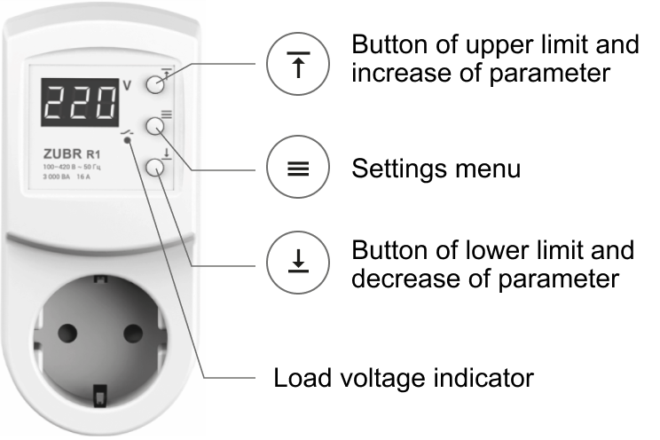
When the device is turned on, it displays the current value of the mains voltage. If the voltage is within the permissible limits, the load is switched on and the green indicator lights up. If the voltage exceeds the upper limit, its value will blink alternating with "U——", if it exceeds the lower limit, its value will blink alternating with "U_ _".

Setting trip limits

(factory setting 242 V and 198 V)
When setting the trip limits, refer to the technical documentation for the protected equipment.

‍To view the upper limit, press "Image", button, to view the lower limit, press "Image" button. Then use "Image" and "Image" buttons to change the limit as necessary.

Button lock

‍Hold the buttons "Image" and "Image"  for more than 6 sec until the message "Loc" ("oFF") appears on the screen.

Reset to Factory Settings

Hold three buttons for more than 12 sec until "dEF" message appears on the screen. When you release the button, the settings are reset and the device reboots.

Menu button "≡"

Menu button ""

Press "≡" to select a menu item.

‍To change the parameters, use "Image" or "Image" The first press on "Image" or "Image" causes the parameter to flash, the next press changes it. The display returns to the mains voltage display 5 seconds after the last press.

Possible issues and solutions

Possible issues
and solutions

At turning on neither the indicator nor the screen don't light up

Screen normal voltage level, load is not turning on

The load is disabled, "oht" flashes on the screen

Every 5 sec the screen displays "Ert"

Additional information

Additional information

Firmware version
Hold "≡" for 6 sec. The manufacturer reserves the right to modify the firmware to enhance the device technical characteristics. Print manual ZUBR R1
version: dtr10.1 | dtr.82.0.5 | 157
Technical support chat
If you haven't found the answer, please contact our technical support engineer: support@dse.com.ua Instagram Telegram
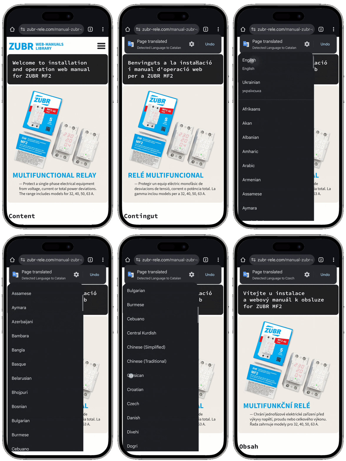
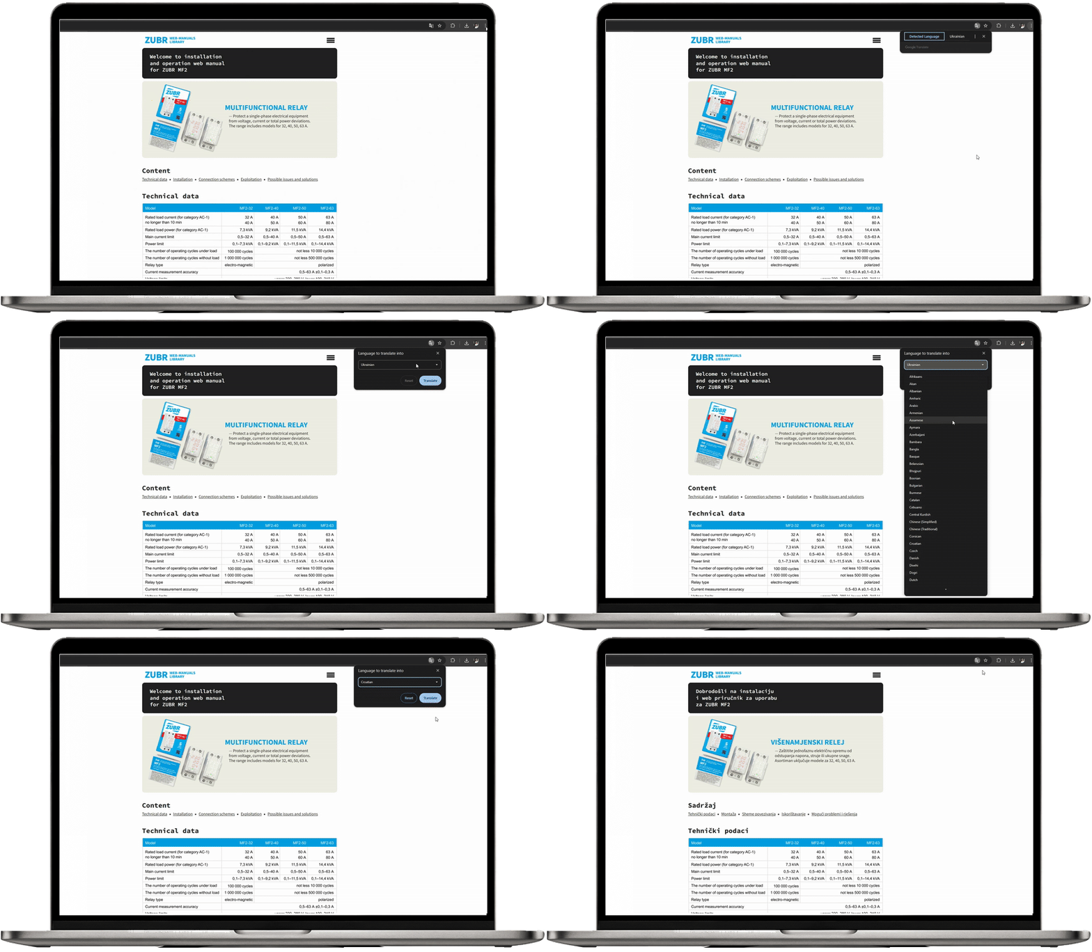
Click three dots in the top corner ➔ select "Translate" ➔ click three dots again ➔ "Choose language"