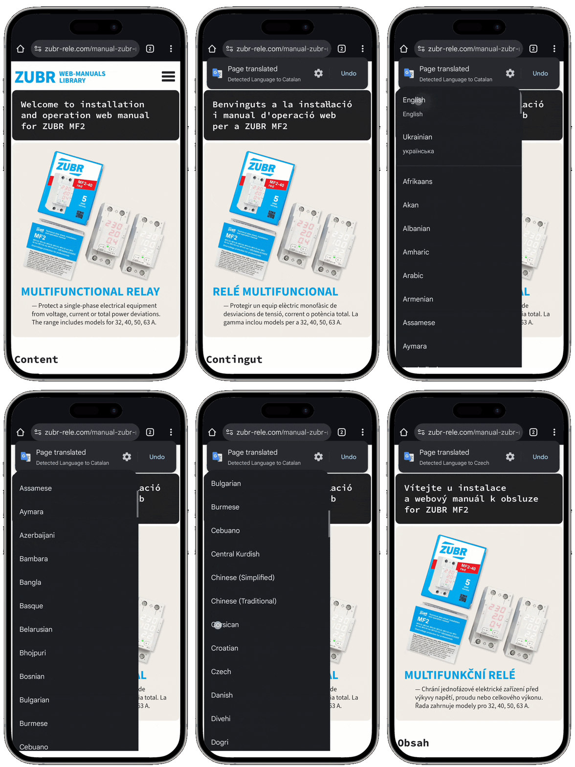
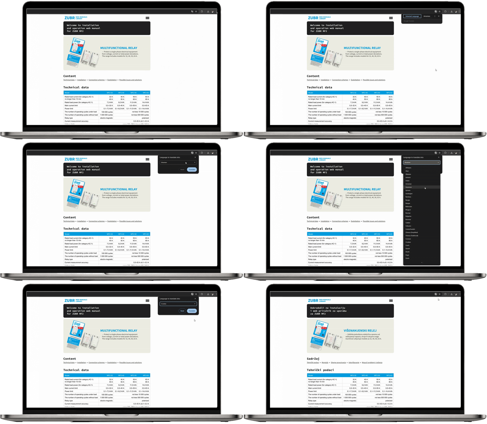
For your convenience, we have adapted the printed manuals into a user-friendly web format.
ZUBR voltage monitoring relay web-manuals library:
• Basic voltage monitoring relay ZUBR D • Basic with thermal protection ZUBR Dt • With maximum function ZUBR D2 • With maximum function plus current and power control ZUBR CV2 [2 screens] • With maximum function plus current and power control ZUBR MF2 [3 screens] • Three-phase Voltage relays with two modes: single-phase and three-phase load ZUBR D6 • Voltage relay with touch buttons in socket ZUBR SR1 • Voltage relay in socket ZUBR R1 • Three-phase ZUBR 3F
Each manual includes a description of functions, wiring diagrams, and setup guidance — everything you need for proper installation and use.
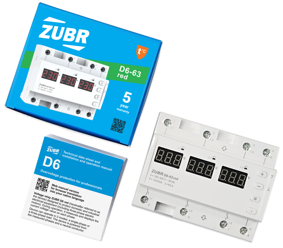
Welcome to installation and operation web manual for ZUBR D6
Voltage relays with two modes: single-phase and three-phase load
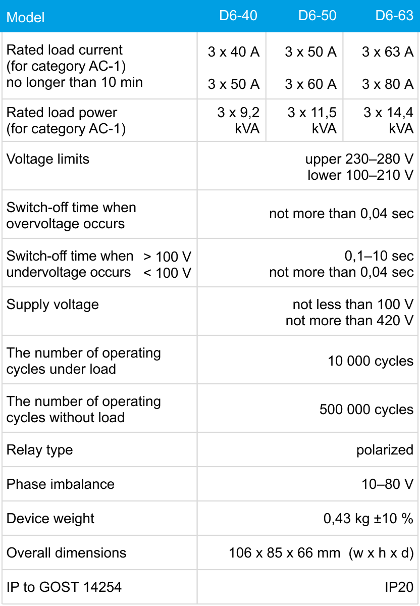
— Protect domestic and industrial electrical equipment (including three-phase electric motors). During operation, it measures and displays the current voltage value on each phase. The range includes models for 40, 50, 63 A.
The appliance is intended for installation inside residences. The risk of moisture or humidity in the installation site should be minimal. The ambient temperature during the installation should be within –5...+45 °С.
The appliance is installed in a special box, which allows to conduct the easy installation and operation. Cabinet should be equipped with standard mounting rail 35 mm width (DIN rail). The appliance takes in width of six standard module on 18 mm. The height of the appliance should be in the range 0,5...1,7 m from the floor.
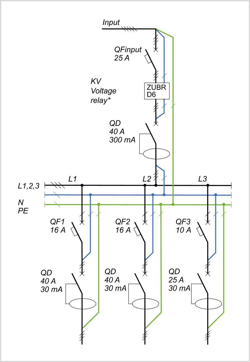
For protection against short circuit and excess capacity in circuit load necessarily need to set in front of the appliance, the automatic circuit-breaker (QF). The automatic switch off is established in the open-phase fault wire, as shown at the schemes 1, 3. To protect person from electric shock leak is set safety shutdown device.
Terminals of the device designed for wire cross section 2 up to 16 mm². It is advisable to use a soft wire, which is tightened in the terminals with a screwdriver with a tip width of no more than 6 mm with a torque of 2,4 N·m. A screwdriver with a blade more than 6 mm wide can cause mechanical damage to the terminals. Doing so will void your warranty claim.
Connection schemes
Connection schemes
The phases and a neutral conductor for measurement and power supply are determined by an indicator and supplied to the device. The connecting wires of the load phases are connected to the corresponding terminals 5–7 (L1–L3), and the neutral conductor (N) to terminal 8.
Important❗️ Before the installation and operation of the device, please read by the end of this document. This will help to avoid possible danger, mistakes, and misunderstandings.
*For correct operation of ZUBR D6, it is enough to connect the neutral conductor to one of the neutral bypass (4 or 8).
Scheme 1. Option for connecting an RCD, a circuit breaker with a neutral bypass through the device to a three-phase load.
Scheme 2. Option for connecting an RCD, a circuit breaker with a neutral bypass through the device to three single-phase loads.
Scheme 3. Wiring diagram
Exploitation
Exploitation
The device can operate in two modes: single-phase or three-phase load. To select a mode, hold down "≡" for 6 sec, use "+" or "–" to select a desired mode. When the mode is changed, the event log is automatically cleared.
The single-phase load mode (asynchronous mode)
The device is capable of performing the functions of three single-phase relays.
Settings and control are separate for each power relay, while the device protects the equipment from voltage going beyond the permissible limits.
The three-phase load mode (synchronous mode)
Settings and control are shared for all power relays, while the device protects the equipment from voltage going beyond the permissible limits and monitors phase asymmetry, phase sequence, and phase loss (these functions can be disabled).
Setting voltage limits
(factory setting 253 V and 198 V)
To view the upper limit of each phase, press "+", and the lower limit — "–". To change the selected limit, press "+" and "–". Important❗During voltage limits settings use technical documentation for protected equipment. All settings are stored in non-volatile memory.
In single-phase mode, first press "≡" to select the desired phase.
If you are using the ZUBR in three-phase mode, the upper and lower limit settings are the same for all three phases.
Log of events for 100 notes
To enter the log, press "i". The screen will display the total number of event records in the log. To view faults separately for each phase, press "≡". Use "+" and "–" to navigate through the log. The log can store up to 99 faults in non-volatile memory, where "n 1" is the most recent and "n99" is the oldest.
To reset the log
Enter the Log and hold down "≡" for 3 sec until "Err rSt" appears. After releasing the button, the log will be cleared. The log will be automatically reset when switching between single-phase and three-phase load modes.
Open to see all examples for different notes
Examples for notes
Upper limit events
Lower limit events
Upper limit events
Lower limit events
An events due to break of the neutral conductor
An events as a result of incorrect relay status
An events due to break of the neutral conductor
An events as a result of incorrect relay status
Overheating events
Accident due to violation (three-phase mode only)
Overheating events
Accident due to violation (three-phase mode only)
Phase imbalance events (three-phase mode only)
Initially, the screens display for 3 sec: the log entry number, the numbers of the phases between which the skew imbalance, and the skew value. For the next 3 sec, the screens show the voltage values on the phases between which there was an skew.
Use the "+" and "–" buttons to change the parameters. After pressing the button for the first time, the parameter will flash, after pressing it for the second time the parameter will change. After 10 sec after pressing — return to the previous state or menu level.
✅ Basic settings [press menu button]
✅ Advanced settings [hold menu button for 3 sec]
✅ Additional settings for three-phase mode[hold menu button for 9 sec]
Possible issues and solutions
At turning on neither the indicator nor the screen don't light up
Screen normal voltage level, load is not turning on
The load is disabled, "oht" flashes on the screen
Every 5 sec the screen displays "Ert"
Every 10 sec the screen displays "Erb", the device does not respond to button presses
Every 5 sec the screen displays "Ern"
The load is disabled, the screen displays "rEP"
Frequent load trip
"ErL" [Error relay] flashes on the screen of one of the phases
Additional information
Locking the buttons
To lock (unlock), hold down the "+" and "–" buttons for more than 6 sec until the message "Loc" ("unLoc") appears on the screen.
Reset to Factory Settings
To reset the factory settings, hold the three buttons "+", "–" and "≡" at the same time for more than 12 sec until "dEF" message appears on the screen. After release, reset to factory settings and reboot will take place, the events log is cleared.
Counter of operation cycles
To view hold the button "і" for 12 sec. Do not discharged.
Temperature of the internal overheating sensor
Hold the button "і" for 18 sec.
Calculated linear stresses
Hold the button "і" for 3 sec. At the corresponding screens, the phase numbers will appear, between which linear voltages are calculated. When releasing the screens for 30 sec calculated linear voltages will be displayed with an accuracy of 2-5 V.
Firmware version
Hold down "i" for 6 seconds. The version is displayed as a moving line. The manufacturer reserves the right to modify the firmware to improve the performance of the device. Print manual ZUBR D6 version: d6.0.76.3.4