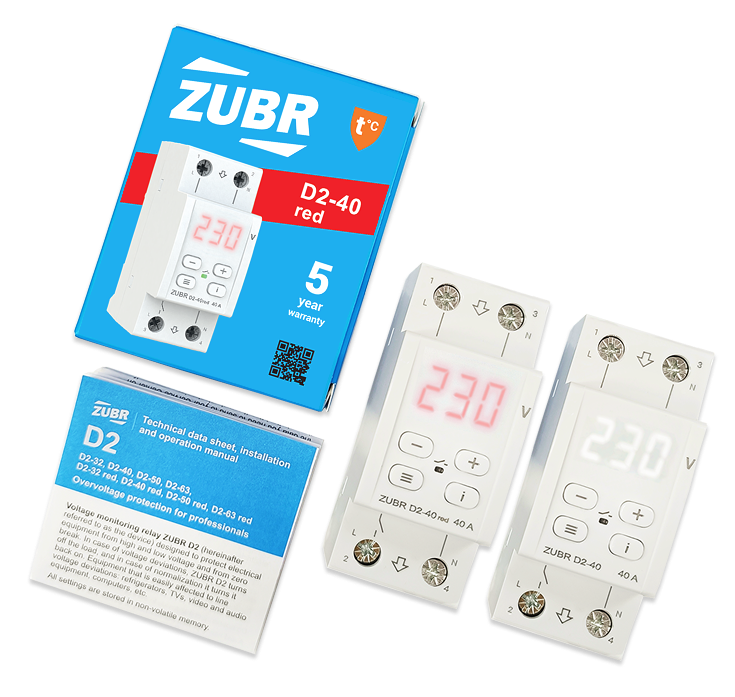
Welcome to installation and operation web manual for ZUBR D2

Voltage monitoring relay

— Protect electrical equipment from critical mains voltage surges. Equipment sensitive to line voltage deviations: refrigerators, TVs, video and audio equipment, computers, etc. The range includes models for 32, 40, 50, 63 A.

Content

Content

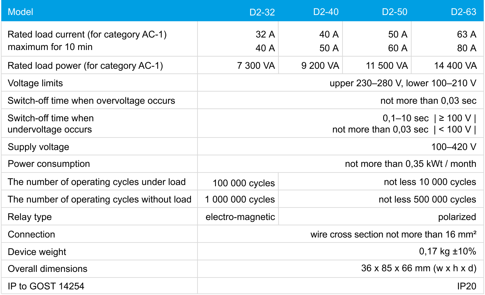
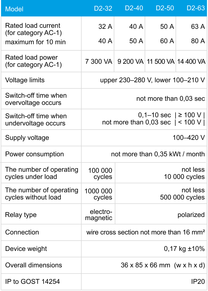
Technical data

Technical data

read more
The number of operating 
cycles under load
100 000 cycles
not less 10 000 cycles
The number of operating 
cycles without load
1 000 000 cycles
not less 500 000 cycles
Relay type
electro-
magnetic
polarized
Current measurement 
accuracy
0,5–63  А ±0,1–0,3 А
Voltage limits
upper 230–280 V,
lower 100–210 V
Switch-off time when
overvoltage occurs
not more than 0,03 sec
Switch-off time when
undervoltage occurs
0,1–10 c  | ≥ 100 V |
not more than 0,03 с  | < 100 V |
Supply voltage
100–420 V
Power consumption
not more than 0,35 kWt / month
Connection
wire cross section not more than 16 mm2
Device weight
0,19 kg ±10%
Overall dimensions
36 х 85 х 66 mm  (w х h х d)
IP to GOST 14254
IP20
close

Installation

Installation

The device is intended for indoor installation. Minimize the risk of moisture and liquid ingress at the installation site. The ambient temperature during operation and installation should be between –5...+45 °С.

‍The appliance is installed in a special box, which allows to conduct the easy installation and operation. Cabinet should be equipped with standard mounting rail 35 mm width (DIN rail). The appliance takes in width of 2 standard module on 18 mm. The height of the appliance should be in the range 0,5...1,7 m from the floor.

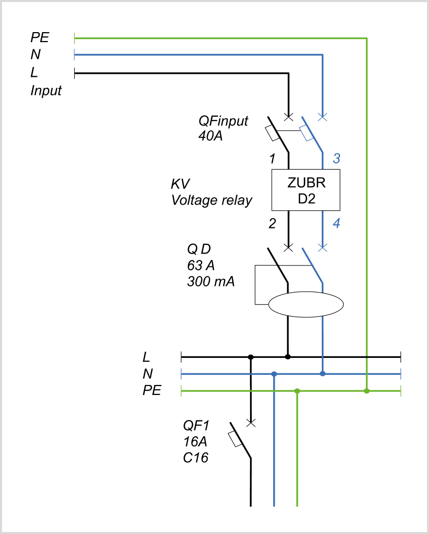
‍For protection against short circuit and excess capacity in circuit load necessarily need to set in front of the appliance, the automatic circuit-breaker (QF), see schemes 1, 3. To protect person from electric shock 
leak is set safety shutdown device.

‍Terminals of the device designed for wire cross section up to 16 mm². Clean the end wires of 10±0,5 mm. It is advisable to use a soft wire, which is tightened in the terminals with a screwdriver with a tip width of no more than 6 mm with a torque of 2,4 N·m. A screwdriver with 
a blade more than 6 mm wide can cause mechanical damage to the terminals. Doing so will void your warranty claim.

Сonnection schemes

Сonnection schemes

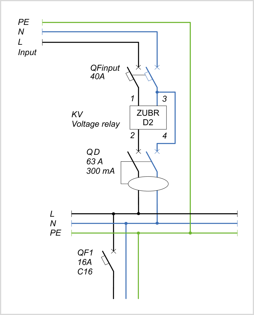
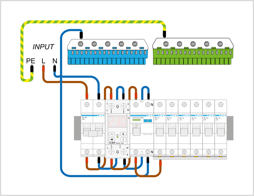
‍Supply voltage (100 ~ 420 V, 50 Hz) served on terminals 1 and 2, phase (L) is connected to terminal location 1, the neutral conductor (N) to terminal 2.

‍The connecting voltage wires connected to terminal 3 and 4: phase (L) is connected to terminal location 3 and the neutral (N) to terminal 4. If a circuit without bypass of neutral through D2 is used, the neutral wire can also be connected to terminal 4.

Important❗️ Before the installation and operation of the device, please read by the end of this document. This will help to avoid possible danger, mistakes, and misunderstandings.

Scheme 1. Electrical diagram witha neutral bypass 
in ZUBR
Scheme 2. Electrical diagram withouta neutral bypass in ZUBR
Scheme 3. Wiring diagram with a neutral bypass 
in ZUBR
Scheme 4. Wiring diagram without a neutral bypass 
in ZUBR

Exploitation

Exploitation

‍When connected and during operation, the thermostat displays the current temperature of the remote sensor. If it is lower than the set temperature, the load is energized. In this case, the indicator lights up red.

‍Use "+" or "–" buttons to change the heating temperature. First, the screen displays the operating mode, then the set temperature of this mode.

If you want to securely protect the settings from children or unauthorized access, press and hold the "+" and "–" simultaneously for 6 seconds until "Loc" appears on the screen, or in case of unlocking, "unLoc" will appear.
After being turned on, the device will display the mains voltage value. If the voltage is within the acceptable range, the load will be activated, indicated by the green indicator. If the voltage exceeds the set limits, the device will turn off the load, and the emergency voltage value will alternate with the fault type screen, where 
U ¯ ¯ indicates exceeding the upper limit, and U_ _ indicates a drop below the lower limit.

Setting voltage limits

(factory setting 242 V and 198 V)
To view the upper limit press "+" button, lower limit press "–" button. To change use "+" and "–" buttons.
Important❗️ During voltage limits settings use technical documentation for protected equipment. All settings are stored in non-volatile memory.

Locking the controls

Hold down the "+" and "–" buttons for more than 
6 seconds until the message "Loc" / "unLoc" appears on the screen.

Log of events for 100 notes

The accidents in the log are displayed in order from newest to older. To access the log, use "i", to navigate through the log, use "+" and "–". To quickly view 
the events, hold down "i".
The value of each event is accompanied by a single flash of display with its number, where "n 0" — is the newest and "n99" — is the oldest.
To reset the log, wait until the device returns to the mains voltage display. Then hold down the "i" button for 3 sec until "rSt" appears. After releasing the button, the log will be cleared.

Reset to Factory Settings

Hold "+" and "–" until "dEF" message appears on the screen. After release, reset to factory settings and reboot will take place, the event log is cleared.
Counter of operation cycles
Hold "і" for 12 seconds. Not discharged.

Menu button "≡"

Menu button ""

Use the "≡" button to navigate through the menu.
Use the "+" and "–" buttons to change the parameters. After first pressing parameter will flash, after second pressing it will change. After 10 seconds after pressing — display returns to the mains voltage. To browse the abbreviation expansion of parameters, use the "і" button.

✅ Basic settings [press menu button]

Possible issues and solutions

Possible issues
and solutions

At turning on neither the indicator nor the screen don't light up

Screen normal voltage level, load is not turning on

The load is disabled, "oht" flashes on the screen

The load is disabled, the screen displays "rEP"

Every 5 sec the screen displays "Ert"

Additional information

Additional information

Firmware version
Hold "і" for 6 sec. The manufacturer reserves the right to modify the firmware to enhance the device technical characteristics. Print manual ZUBR D2
version: d2.1.3G.34.5
Technical support chat
If you haven't found the answer, please contact our technical support engineer: support@dse.com.ua Instagram Telegram
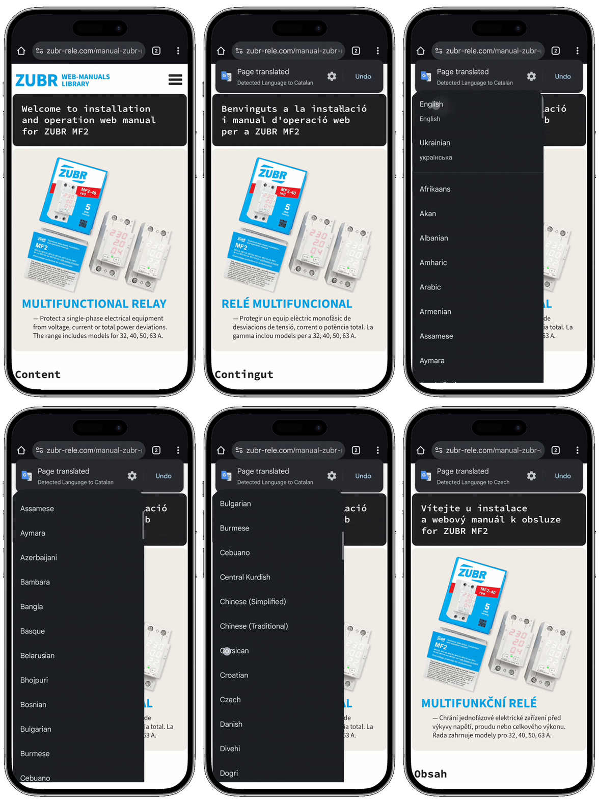
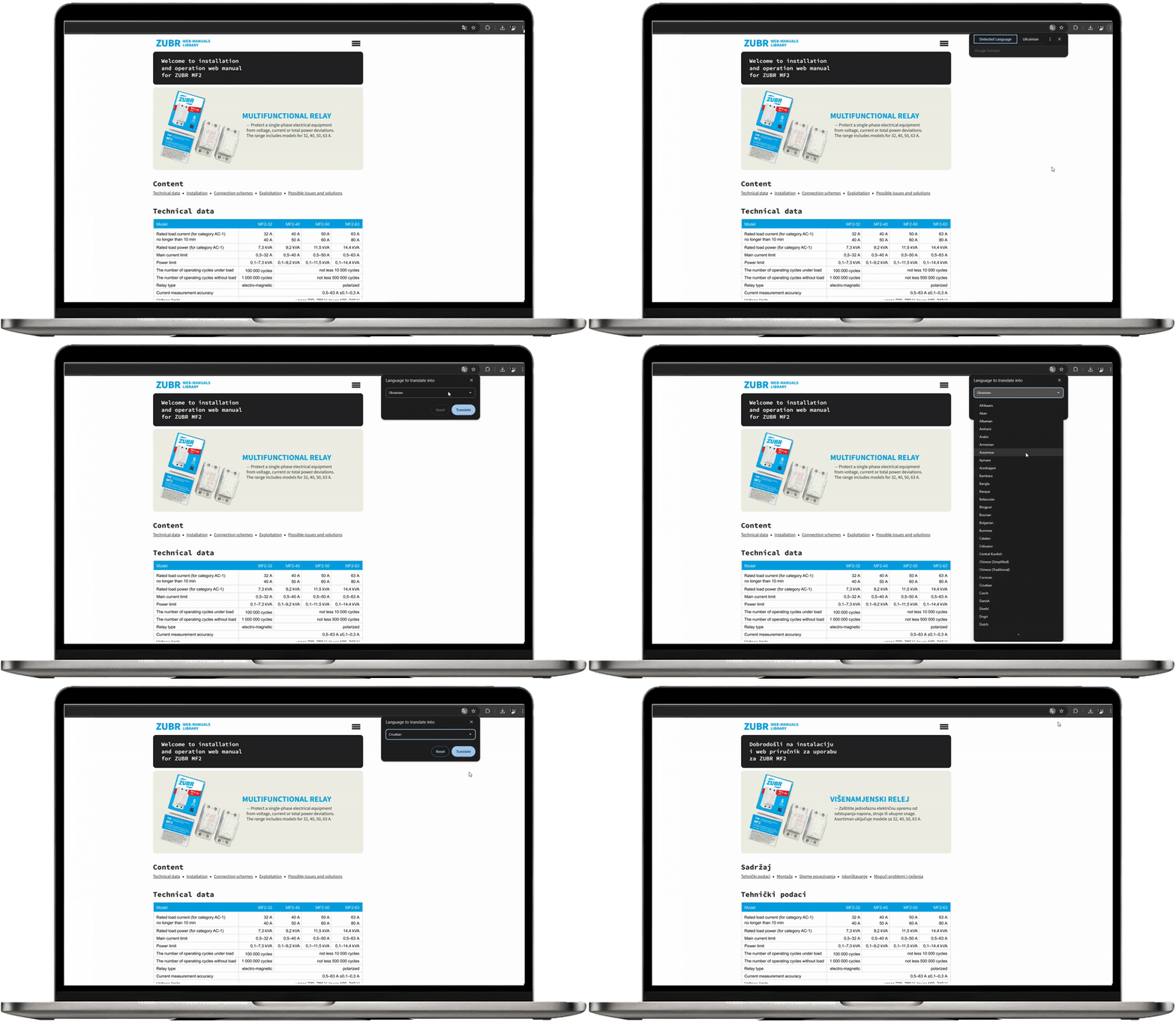
Click three dots in the top corner ➔ select "Translate" ➔ click three dots again ➔ "Choose language"