For your convenience, we have adapted the printed manuals into a user-friendly web format.
ZUBR voltage monitoring relay web-manuals library:
• Basic voltage monitoring relay ZUBR D
• Basic with thermal protection ZUBR Dt
• With maximum function ZUBR D2
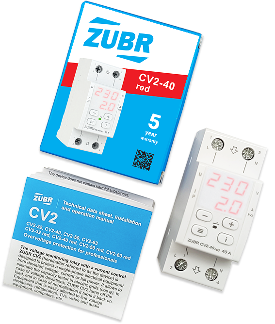
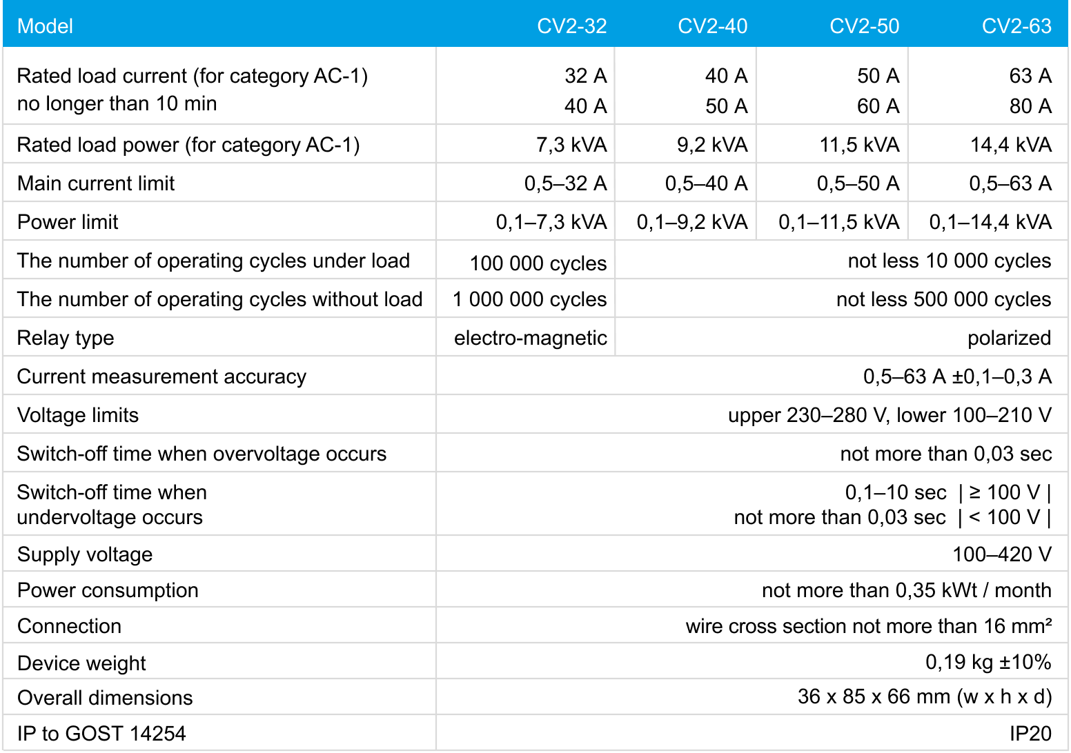
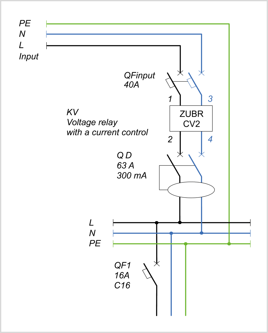
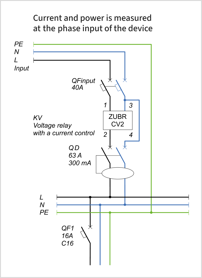
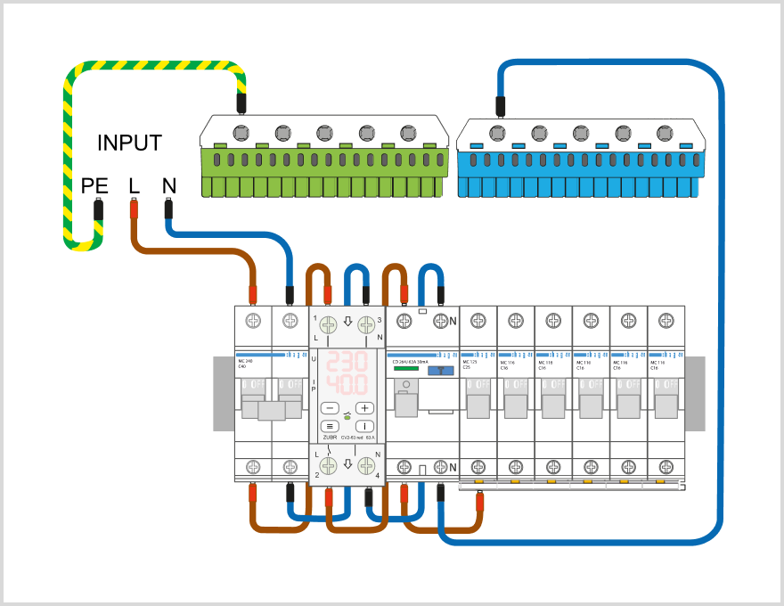
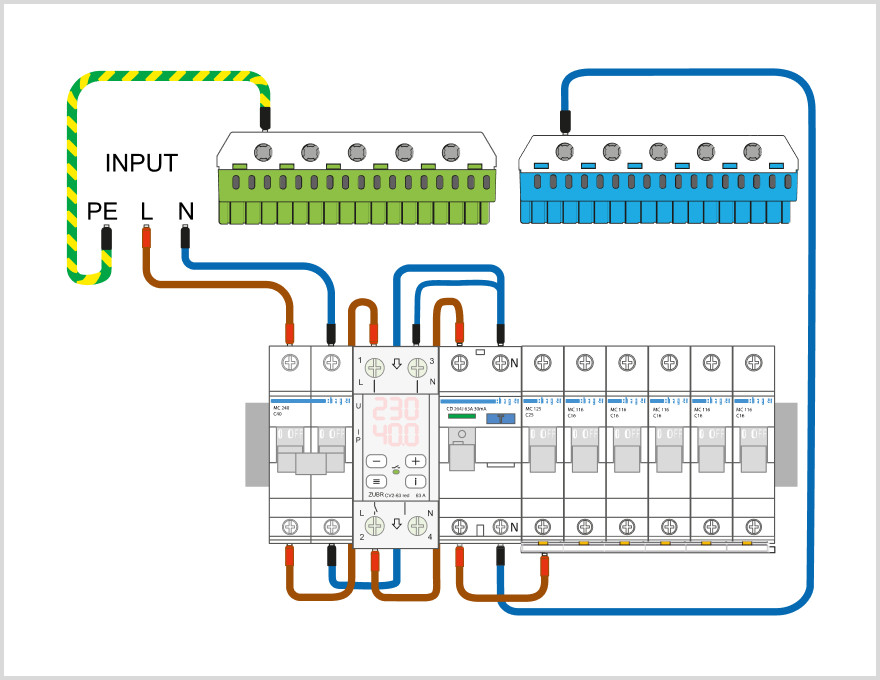
• With maximum function plus current and power control ZUBR CV2 [2 screens]
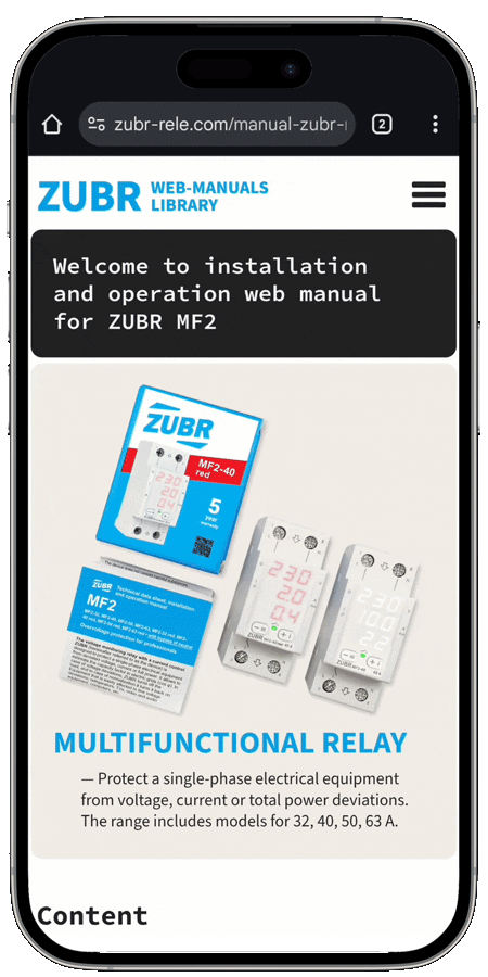
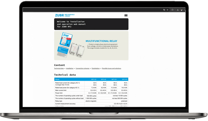
• With maximum function plus current and power control ZUBR MF2 [3 screens]
• Three-phase Voltage relays with two modes: single-phase and three-phase load ZUBR D6
• Voltage relay with touch buttons in socket ZUBR SR1
• Voltage relay in socket ZUBR R1
• Three-phase ZUBR 3F
• Basic with thermal protection ZUBR Dt
• With maximum function ZUBR D2
• With maximum function plus current and power control ZUBR CV2 [2 screens]
• With maximum function plus current and power control ZUBR MF2 [3 screens]
• Three-phase Voltage relays with two modes: single-phase and three-phase load ZUBR D6
• Voltage relay with touch buttons in socket ZUBR SR1
• Voltage relay in socket ZUBR R1
• Three-phase ZUBR 3F
Each manual includes a description of functions, wiring diagrams, and setup guidance — everything you need for proper installation and use.